The LCD1602 is a very famous LCD that can be connected to various devices such as the Raspberry Pi. The LCD1602 on its own is quite tricky to wire it up since it requires 16 pins to be connected. The LCD1602 can also be purchased with an I2C module, which reduces the amount of pins needed to just 4.
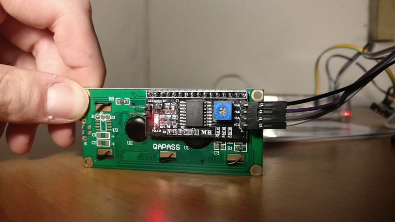
For this tutorial, we’ll be working with a LCD1602 with an I2C module. I got mine from AliExpress for around $2.50. Make sure to grab a set of jumper cables as you’ll need them to connect the LCD to the Raspberry Pi. I got mine from AliExpress as well for around $1.50.
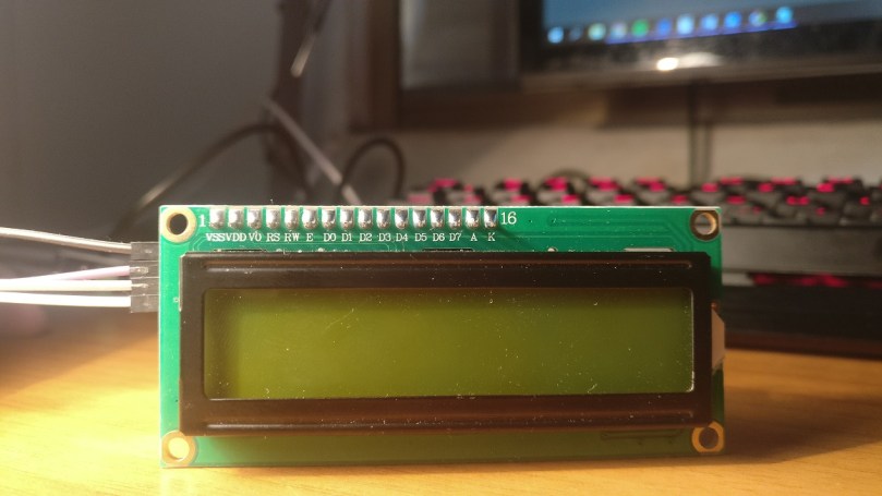
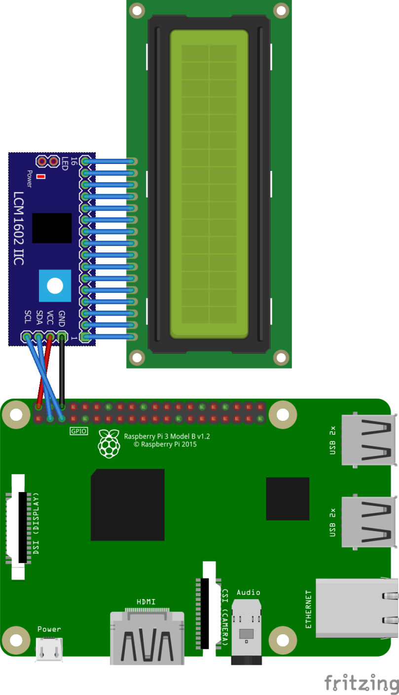
Let’s start by wiring it up. We have 4 pins connect – GND (ground), VCC (power, 5V), SDA (data line) and SCL (clock line). GND and VCC can be connected to any equivalent GND and 5V pin. SDA and SCL should be connected to pins BCM 2 and BCM 3 accordingly.
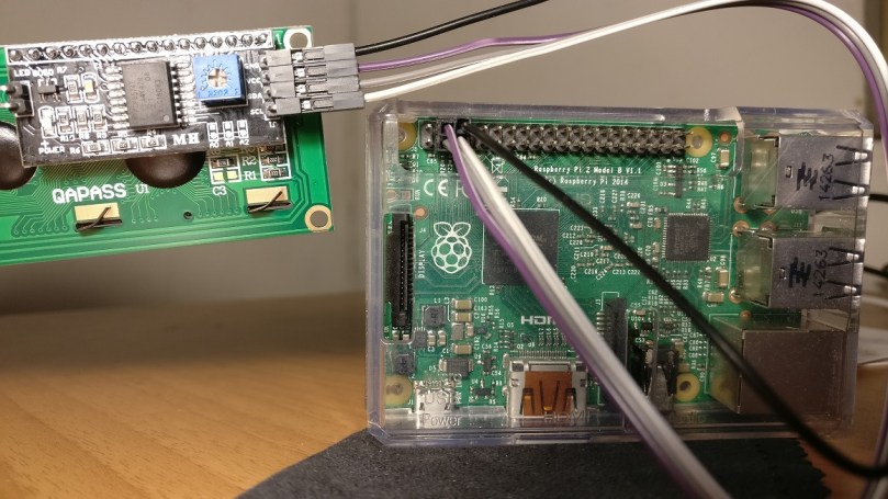
If you’re following the Raspberry Pi Temperature Monitoring Part 1 and connected the DS18B20 temperature sensors, you should now have the following configuration.


Great! We’re done from the hardware’s side – let’s start configuring our Raspberry Pi to communicate with our LCD.
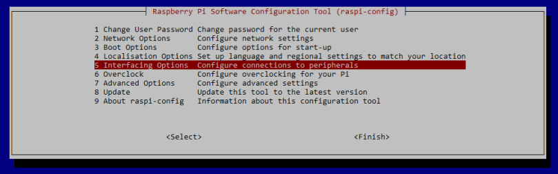
Firstly, let’s enable I2C from the Raspberry Pi Config. Fire up the raspi-config to get started: sudo raspi config
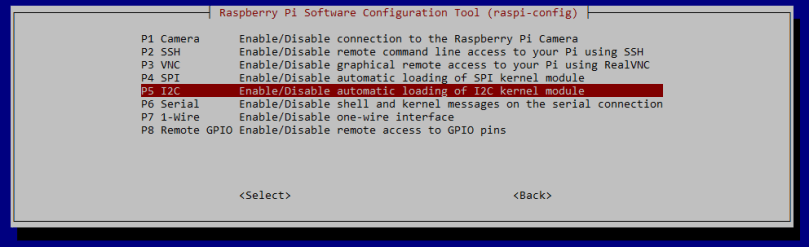
Now navigate to Interfacing Options => I2C => Enable I2C
Now that we’ve enabled I2C communication, it’s time to start development! We’ll need to get some tools before we start working though, so fire up a shell and input:
sudo apt-get install i2c-tools.
Once that’s done, the LCD is ready to be programmed! Let’s make sure that the LCD is properly connected and working. In a shell, type:
i2cdetect -y 1.
The output should be something like the below. Note the number outputted by the command; will be needed later on. We’ll need this address when we’re trying our demo code. In this case, the address is “27”.

Great! Now, it’s time to test out our display and see if it works! We’ll be using a Github library – https://github.com/albertherd/LCD1602. This has been forked from https://github.com/bitbank2/LCD1602. We’ll be using my fork since the original repository has an unresolved issue with clearing the display.
After you’ve cloned the repository in your working directory, it’s time to use the address (27 in my case) obtained earlier. Open the main.c and find the call to lcd1602Init and change second parameter. This is how it looks in my case:
lcd1602Init(1, 0x27);
Now it’s time to compile and run our code. If all goes well, we should be getting some text on the screen. You can change the text to whatever you’d like by changing the following lines in main.c.
lcd1602WriteString("BitBank LCD1602");

lcd1602SetCursor(0,1);

lcd1602WriteString("ENTER to quit");
Build and run using the following commands:
make

make -f make_demo

./demo
The screen should look like the below:

Great! Now we’ve successfully connected our LCD1602 to our Raspberry Pi and we’re able to output content on it!
In the next part of this tutorial series, we’ll start by capturing the temperature using the sensor in our first part of the tutorial and outputting it! Stay tuned.
