Outputting DS18B20 temperatures on a LCD1602 – Raspberry Pi Temperature Monitoring Part 4

This is part of a tutorial series. If you feel a bit lost, I suggest following the tutorial in order:

Just interested in the code? – https://github.com/albertherd/DS18B20Reader

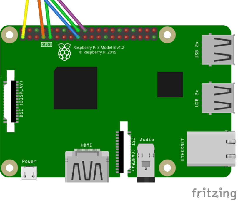
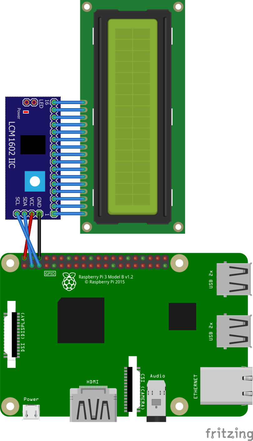
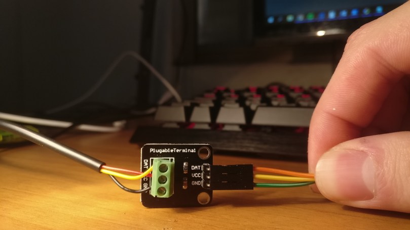
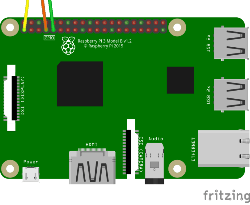
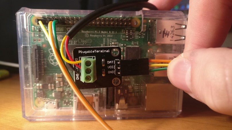
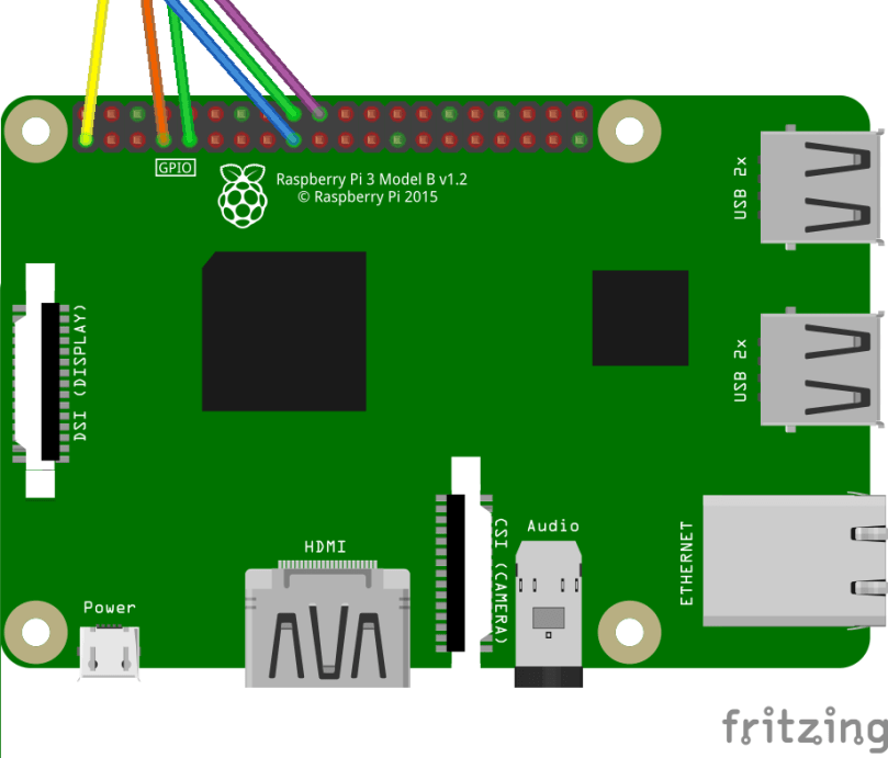
This article assumes that you’ve configured one or more DS18B20 sensors to your Raspberry Pi and configured your Raspberry Pi to work with an LCD1602. If you did not, read the above mentioned links.

Okay – this should be a quick post – most of the heavy lifting is done. Remember the LCD1602 library that we’ve used in the second tutorial? We’ll be using that to simply get the temperature we’ve captured in third tutorial and display it.

We’ll need to do the following changes:

  1. Import the LCD1602 library.
  2. Initialize the LCD1602 on application startup.
  3. Read and display information on the LCD1602.
  4. Cleanup resources before exiting – this is important since we’ll need to turn off the backlight after usage.

Import the LCD1602 library

Get a copy of this repository – either by cloning or simply copying lcd1602.c and lcd1602.h files to your solution. We’ll be also adding them to our CMake file – it should look something of the sort. I’ve left the solution on debug in this case.

set(SOURCE main.c sensor.c lcd1602.c main.h sensor.h lcd1602.h)
set(CMAKE_BUILD_TYPE Debug)
add_executable(DS18B20Reader ${SOURCE})

Now it’s simply just adding a reference to the lcd1602.h in the solution. Next!

Initialize the LCD1602 on application startup

We’ll need to initialize the library and open a connection to the display under the right address – check your device address by checking the third tutorial. To simplify things, I hard-coded the value which is 0x27 in my case. Call this when initializing the application.

void InitializeLCD()
{
    int rc;
	rc = lcd1602Init(1, LCDADDRESS);
	if (rc)
	{
		printf("Initialization failed; aborting...\n");
		return;
	}
}

Read and display information on the LCD1602

We’ll be modifying our main loop to output content to the console (not important though and output to the LCD1602 screen. The main adjustment we’ve did in the main loop is that we’ve broken down our output to two functions – Outputting to console (not important) and outputting to the LCD1602 – Let’s see the main loop:

void ReadTemperatureLoop(SensorList *sensorList)
{
    while(!sigintFlag)
    {
        for(int i = 0; i SensorCount; i++)
        {
            float temperature = ReadTemperature(sensorList->Sensors[i]);
            PrintTemperatueToLCD1602(sensorList->Sensors[i], i % LCD1602LINES, temperature);
            LogTemperature(sensorList->Sensors[i], temperature);
        }       
    }
}

Let’s now have a look at the important method – PrintTemperatueToLCD1602. Keeping in mind that the LCD1602 has two lines, we’ll be receiving the calculated line number as a parameter. This will make sure that values will lie between 0 and 1 only using modulus.

We’ll also need to remember that each line will hold up to 16 characters, so we’re truncating anything more than 16 characters (actually 16 + 1 for null termination). We’ll then just pass the (potentially truncated) string to the LCD1602 and et voila!

void PrintTemperatueToLCD1602(Sensor *sensor, int lineToPrintDataOn, float temperature)
{
    char temperatureString[LCD1602CHARACTERS + 1];
    snprintf(temperatureString, LCD1602CHARACTERS + 1, "%s : %.2fC", sensor->SensorName, temperature);

    lcd1602SetCursor(0, lineToPrintDataOn);
    lcd1602WriteString(temperatureString);
}

Cleanup resources before exiting

After we’re done, it’s just a matter of cleaning up resources. As previously mentioned, this is important since we’ll need to turn off the backlight after usage. In the cleanup method, we’re just calling the lcd1602Shutdown method.

void Cleanup(SensorList *sensorList)
{
    printf("Exiting...\n");
    FreeSensors(sensorList);
    lcd1602Shutdown();
}

Fetch a complete copy of the code from from GitHub – https://github.com/albertherd/DS18B20Reader

Let’s run the application! In a terminal with git and cmake installed, run the following commands

git clone https://github.com/albertherd/DS18B20Reader
cd ./DS18B20Reader
cmake . && make && ./DS18B20Reader "Sensor"

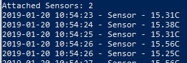
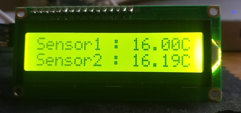
With some luck, your LCD1602 should display something like the below. In my case I have two sensors so I’ve fired up the application using the following syntax:

./DS18B20Reader "Sensor1" "Sensor2"

LCD1602OutputCropped

Until the next one!

Using C to monitor temperatures through your DS18B20 thermal sensor – Raspberry Pi Temperature Monitoring Part 3

This is part of a tutorial series. If you feel a bit lost, I suggest following the tutorial in order:

Just interested in the code? – https://github.com/albertherd/DS18B20Reader

Since you made it here, great! Your Raspberry Pi should have one or more DS18B20 thermal sensors connected, like the image below.

sensor2.png

Now that we have our DS18B20 thermal sensor connected to our Raspberry Pi, it’s time to do some programming to read out the temperature! Our application will need to be able to the following tasks:

  1. Discover all the DS18B20 sensors (in my case, I’ve connected 2 but this application should handle an arbitrary number of sensors).
  2. Assign a friendly name so we’ll know which sensor is which and store them in a list.
  3. Retrieve and parse the information from the device.
  4. Do whatever necessary with the gathered information.

1) Discover all the DS18B20 sensors

First and foremost, our code cannot just assume that devices just exist on the system – we’ll need to go and discover these devices. Since the DS18B20 makes use of the 1-Wire protocol, devices will live under the /sys/bus/w1/devices/ directory. Therefore, our code will need to devices living under this directory, whose names start with 28 since all DS18B20 device names will start with 28. Let’s start by knowing how many devices are connected.

typedef struct Sensor
{
    char *SensorName;
    FILE *SensorFile;    
} Sensor;
 
typedef struct SensorList
{
    Sensor **Sensors;
    int SensorCount;
} SensorList;

DIR *dir;
struct dirent *dirEntry;

SensorList *sensorList = malloc(sizeof(SensorList));
sensorList->SensorCount = 0;

if(!(dir = opendir("/sys/bus/w1/devices/")))
    return sensorList;

while((dirEntry = readdir(dir)))
{        
    if(strncmp(dirEntry->d_name, "28", 2) == 0)
    {
        sensorList->SensorCount++;
    }
}

2) Assign a friendly name so we’ll know which sensor is which and store them in a list

Now that we’ve discovered the devices connected to the system, it’s time to save a reference and optionally a friendly name as well. Logic mostly applies from step 1.

sensorList->Sensors = malloc(sizeof(Sensor*) * sensorList->SensorCount);
Sensor **currentSensor = sensorList->Sensors;   

int sensorNamesAllocated = 0;
while((dirEntry = readdir(dir)))
{        
    if(strncmp(dirEntry->d_name, "28", 2) == 0)
    {   
        char *sensorName;
        if(sensorNamesCount > sensorNamesAllocated)
        {
            sensorName = strdup(*sensorNames);
            sensorNames++;
        }
        else
        {
            sensorName = strdup("Sensor");
        }

        char sensorFilePath[64];     
        sprintf(sensorFilePath, "%s%s%s",  "/sys/bus/w1/devices/", dirEntry->d_name, "/w1_slave");
        *currentSensor = GetSensor(sensorFilePath, sensorName);
        currentSensor++;
    }
}

Sensor *GetSensor(char *sensorId, char *sensorName)
{
    Sensor *sensor = malloc(sizeof(Sensor));
    sensor->SensorFile = fopen(sensorId, "r");
    sensor->SensorName = sensorName;
    return sensor;
}    

3) Read the temperature from the device

This is the most exciting part – we actually get to read the temperatures! Using the sensor information we got from steps 1 and 2, we can get the device, open it as a file, extract the readings and parse it accordingly. Using the FILE API makes it very easy to do so – grab all the contents and store it in a buffer. As mentioned in the first tutorial, the content of the file looks as follows –

0b 01 55 05 7f 7e 81 66 bf : crc=bf YES
0b 01 55 05 7f 7e 81 66 bf t=16687

We’re only intereested in the t= component, so some string manipulation and float conversion will take the 16687 and convert it into 16.687C. We’re also doing some range checking since the DS18B20 is rated between -55C and +125C

   
long deviceFileSize;
char *buffer;

FILE *deviceFile = sensor->SensorFile;
fseek(deviceFile, 0, SEEK_END);
deviceFileSize = ftell(deviceFile);
fseek(deviceFile, 0, SEEK_SET);

buffer = calloc(deviceFileSize, sizeof(char));

fread(buffer, sizeof(char), deviceFileSize, deviceFile);
char *temperatureComponent = strstr(buffer, "t=");
if(!temperatureComponent)
{
    free(buffer);
    return -1;
}

temperatureComponent +=2; //move pointer 2 spaces to compensate for t=

float temperatureFloat = atof(temperatureComponent);
temperatureFloat = temperatureFloat / 1000;

if(temperatureFloat  125)
    temperatureFloat = 125;    

free(buffer);
return temperatureFloat;

4) Do whatever necessary with the gathered information

We now have the information at hand, great! We can do many sort of things with it, such as sending an email, activating some other device or whatever is necessary. For demo purposes, we’re simply going to output the contents to the console just to see it working. This is in a loop so we’ll keep reading the temperature until the application exits.

 while(1)
    {
        for(int i = 0; i SensorCount; i++)
        {
            char dateTimeStringBuffer[32];
            strftime(dateTimeStringBuffer, 32, "%Y-%m-%d %H:%M:%S", localtime(¤tTime));

            float temperature = ReadTemperature(sensorList->Sensors[i]);
            printf("%s - %s - %.2fC\n", dateTimeStringBuffer, sensorList->Sensors[i]->SensorName, temperature);
        }       
    }

To try out the code as a whole solution, grab a copy from GitHub – https://github.com/albertherd/DS18B20Reader

In a terminal with git and cmake installed, run the following commands

git clone https://github.com/albertherd/DS18B20Reader
cd ./DS18B20Reader
cmake . && make && ./DS18B20Reader "Sensor"

If the output looks like the below, congratulations!

ds18b20 tutorial sample output.png

In the next tutorial, we’ll pick up from here and we’ll start outputting the content on an LCD1602! Until the next one.

Connecting a LCD1602 with an I2C module to your Raspberry Pi – Raspberry Pi Temperature Monitoring Part 2

The LCD1602 is a very famous LCD that can be connected to various devices such as the Raspberry Pi. The LCD1602 on its own is quite tricky to wire it up since it requires 16 pins to be connected. The LCD1602 can also be purchased with an I2C module, which reduces the amount of pins needed to just 4.

For this tutorial, we’ll be working with a LCD1602 with an I2C module. I got mine from AliExpress for around $2.50. Make sure to grab a set of jumper cables as you’ll need them to connect the LCD to the Raspberry Pi. I got mine from AliExpress as well for around $1.50.

IMG_20190102_110607.jpg

img_20190109_230900

Let’s start by wiring it up. We have 4 pins connect – GND (ground), VCC (power, 5V), SDA (data line) and SCL (clock line). GND and VCC can be connected to any equivalent GND and 5V pin. SDA and SCL should be connected to pins BCM 2 and BCM 3 accordingly.

lcd1602_i2c_raspberrypi

img_20190109_231321

If you’re following the Raspberry Pi Temperature Monitoring Part 1 and connected the DS18B20 temperature sensors, you should now have the following configuration.

lcd1602_i2c_ds18b20_raspberrypi

img_20190109_232649

Great! We’re done from the hardware’s side – let’s start configuring our Raspberry Pi to communicate with our LCD.

Firstly, let’s enable I2C from the Raspberry Pi Config. Fire up the raspi-config to get started: sudo raspi config

Now navigate to Interfacing Options => I2C => Enable I2C

raspi-config-interfacing-options

raspi-config-interfacing-options-i2c

Now that we’ve enabled I2C communication, it’s time to start development! We’ll need to get some tools before we start working though, so fire up a shell and input:

sudo apt-get install i2c-tools.

Once that’s done, the LCD is ready to be programmed! Let’s make sure that the LCD is properly connected and working. In a shell, type:

i2cdetect -y 1.

The output should be something like the below. Note the number outputted by the command; will be needed later on. We’ll need this address when we’re trying our demo code. In this case, the address is “27”.

i2cdetect

Great! Now, it’s time to test out our display and see if it works! We’ll be using a Github library – https://github.com/albertherd/LCD1602. This has been forked from https://github.com/bitbank2/LCD1602. We’ll be using my fork since the original repository has an unresolved issue with clearing the display.

After you’ve cloned the repository in your working directory, it’s time to use the address (27 in my case) obtained earlier. Open the main.c and find the call to lcd1602Init and change second parameter. This is how it looks in my case:

lcd1602Init(1, 0x27);

Now it’s time to compile and run our code. If all goes well, we should be getting some text on the screen. You can change the text to whatever you’d like by changing the following lines in main.c.

lcd1602WriteString("BitBank LCD1602");
lcd1602SetCursor(0,1);
lcd1602WriteString("ENTER to quit");

Build and run using the following commands:

make
make -f make_demo
./demo

The screen should look like the below:

IMG_20190110_231937.jpg

Great! Now we’ve successfully connected our LCD1602 to our Raspberry Pi and we’re able to output content on it!

In the next part of this tutorial series, we’ll start by capturing the temperature using the sensor in our first part of the tutorial and outputting it! Stay tuned.

Connecting a DS18B20 thermal sensor to your Raspberry Pi – Raspberry Pi Temperature Monitoring Part 1

A project that I’ve been working on during the Christmas holidays was to hook up some thermal probes to my Raspberry Pi, just to play around. This tutorial simply follows the steps that I’ve taken to achieve so.

You’ll need:

  • Raspberry Pi, any flavor as long as it has GPIO headers available. I had a Raspberry Pi 2, so I used that.
  • You’ll also need the usual suspects – USB to MicroUSB to hook it up to power, HDMI to connect it to a display for initial configuration and an ethernet port to manage it through SSH. I highly recommend configuring SSH rather than using the device itself. This tutorial assumes you’re using SSH.
  • A DS18B20 sensor – I’d suggest getting one which includes a Plugable Terminal to avoid soldering – just wire it up and you’re good to go. I got mine from AliExpress
  • Also make sure your kit has 3 jumper cables. They are typically included. Just to be sure, I also got a set of female to female jumper cables from AliExpress though I did not use them for the DS18B20 sensor.

All right, let’s wire it up! The DS18B20 sensor requires three pins – data, VCC (3.3V), and ground. Connect the wires as below. Data is yellow, VCC is red and ground is black.

IMG_20190102_105252

Connect the 3 pins using the jumper cables as shown below.
sensor1.png

IMG_20190102_105726

We’ll also need to instruct the Raspberry Pi that we’re going to connect the DS18B20 sensor. This sensor makes use of the 1-Wire protocol, so let’s activate it:

  • Connect to the Raspberry Pi using SSH
  • Let’s start by editing the config file that the Raspberry PI parses every time it boots up: sudo nano /boot/config.txt
  • Go to the end of the document and input the following. Specifying gpiopin=4 is actually optional since by convention, 1-wire devices are expected on gpiopin 4 on the Raspberry Pi.
    # Enable OneWire Protocol
    dtoverlay=w1-gpio;gpiopin=4
  • Time to reboot the Raspberry Pi sudo reboot
  • Once the Raspberry PI reboots and you re-connect using SSH, it’s time to get data from the sensor! Let’s find the 1-wire devices connected to the system. Let’s start by browsing to the appropriate directory. cd /sys/bus/w1/devices
  • Great! Let’s now see the devices attached to the Raspberry Pi. ls
  • This will get the devices attached using the 1-Wire protocol. You should have a device called 28-xxxxxxxxxxxx (where x stands for your unique 12 digit serial number). Let’s now browse the device. Mine is 28-02199245e07b, so let’s use it an example. cd 28-02199245e07b
  • Once you access the device, there should be a file called w1_slave. Let’s see the contents of the file. cat w1_slave
  • The file should look like this:
    0b 01 55 05 7f 7e 81 66 bf : crc=bf YES
    0b 01 55 05 7f 7e 81 66 bf t=16687
  • If the file looks like the above, great! The temperature component is t=16687. The temperature in this case is 16.687 °C

We also can take this to the next level and add another thermal probe! Attach it as shown below.
sensor2IMG_20190102_110134

This will require re-editing the /boot/config.txt. Let’s do it!

  • Re-open /boot/config.txt – sudo nano /boot/config.txt
  • Go to the end and add the following. I chose pin 24 because it’s easy to wire since it’s close to a 3.3v and ground. dtoverlay=w1-gpio;gpiopin=24
  • Close and save, then cd /sys/bus/w1/devices
  • You should now see two devices as 28-xxxxxxxxxxxx

Of course, at this stage we did get the temperature, but it’s not really usable. We can get access to this information programmatically – this is what we’ll be doing in the next part of this tutorial. We’ll also be eventually showing the information on a separate LCD screen! Stay tuned!

I hate it when my laptop’s fan switches on – here’s how I solved it (Part 1)!

I’ve made it a point that I’d buy my laptop equipped with a Intel U-Based – this is to make sure that my laptop is as light, power efficient and quiet as possible. My HP Spectre X360 does all of this; well almost. It’s light (around 1.3kg), power efficient (8-10 hours of battery plus), but is not the quietest laptop on the planet.

When the laptop has a relatively moderate task to process, it ramps up the CPU to full (3.5 Ghz). That’s great, except for the fact that high clocks generate a lot of heat. When the threshold temperature is constantly exceeded (in my laptop’s case, around 50c), the fan needs to kick-in in order to manage thermals.

There’s nothing wrong with that; the laptop functions perfectly. What I’d like is to do all these tasks, whilst the laptop remains cool and will only require passive cooling. How can this be achieved? By lowering the maximum CPU Clock, of course!

What I ended up doing is setting up the maximum CPU usage to 45% (at around 1.6 Ghz), instead of 100%. This means that tasks run slightly slower, but meaning that the laptop runs way cooler. Even better, most of the time, the performance cost is not felt since the tasks do not actually max the CPU usage; thus a lower CPU clock is sufficient!

For now, I’ve solved it naively – setting up this value as a fixed value is not the most efficient. There are times that my laptop is running well below under the threshold temperature where the fan needs to kick-in. A more intelligent solution is to adjust the temperatures on the fly, so that the laptop maintains a target temperature, much like how NVIDA’s GPU Boost works.

This is very easy to set up – this can be accessed through the Windows Power Options. Here’s a step by step guide.

Power Options
1) Right click the battery icon – select Power Options


Change Plan Settings
2) Select your desired power plan and select Change plan settings


Change Advanced Power Settings
3) Select Change Advanced Power Settings


Max Processor State
4) Scroll down, open Processor power management, open Maximum processor state, and type your maximum value. (Eg 45%)

That’s it! Next time, we’ll see how we can do all this programmatically, through WinAPI.

Until the next one.

You don’t need more than 1080p on a 13″ screen!

Recently, I’ve been on the market to buy a new 13″ Laptop. I ended up buying a HP Spectre x360: i7, 8GB RAM, 1080p touch screen and the usual gizmos. I’ll talk about the huge headache I went through (not counting the hours spent searching reviews) in order to actually determine what I’m going to buy.

I was quite sure on what I wanted – a lightweight 13″ laptop with an i7 and 8GB of RAM and stuff like that. In other words, a really portable machine which won’t slow me down on the go. There were several contenders in this department, the Dell XPS 13, Lenovo Yoga 910, Razer Blade Stealth, the aforementioned HP Spectre x360  and some others which were quickly eliminated from the list. The biggest question was always : 1080p or 4K screen?

People had mixed feelings about this, some said go for 1080p and some said 4K. Here are my thoughts on this subject. Oh, by the way – this argument is only for Windows Based laptops. This does not apply for non-Windows based machines.

Let’s start by the biggest problem that screen size carries. If the pixel count grows and the screen does not, this means that the actual pixel size gets smaller. So, this means that a 300 pixels on a 13″ 1080p might be 4cm long, but 300 pixels on a 13″ 4k might be just 1 cm long. Most (older) applications were designed to work with pixels, so they do not cater for big resolutions on small screens.

Fortunately, Microsoft have realised this problem and provide a feature to scale the size of the display accordingly. So, old applications will scale up to the appropriate size, but this comes at a cost. Most of the time, the bigger the scale, the blurrier the window will actually look; I’ve illustrated this below. One can “clearly” see that the D is quite blurred out.

Scalingblurring

This problem is acknowledged by Microsoft themselves and provide some workarounds for this. Fortunately, as time goes on, more and more applications are being designed with this problem in mind and scale quite nicely. Also, the new UWP applications (such as the new looking applications on Windows 10 – Settings, Calculator and such handle this problem natively; they will not suffer from these problems.

In my case, my 1080P 13″ display came configured out of the box to use 150% scaling. This means that applications that do not handle such scaling will be multiplied by 1.5 times in order to scale appropriately. So the problem with scaling and blurring already exist with a 1080P display, let alone a 4K display! Those apps which scale poorly will simply exhibit worse symptoms since the scaling needs to be bigger at a 4K resolution.

This problem also exists in games; Linus played Half Life on a 16K monitor; scaling was just laughable.

My end verdict? If you’re buying a Windows-Based machine, don’t opt for a 4K on a 13″ display. It will make the scaling problem just worse. Let’s just hope for a better future where all applications scale correctly! I hope I’ll save some time and headache for anyone who is in the market for a 13″ laptop.

I have not mentioned too much technical details on what actually is going on; I do not want to confuse potential non-technical readers. This post will be followed up by a technical blog post explaining what is actually going on and as a programmer, how to program against this problem. If interested though, the problem mostly lies in the domain of DPI and DIP.