Get Files in ZIP file stored on Azure without downloading it

Recently, I was working on a task where we had to get file entries and names off ZIP files stored on Azure. We had terabytes of data to go through and downloading them was not really an option. In the end of the day, we solved this in a totally different way, but I remained curious if this is possible, and it sure is.

The aim is to get all the entry names of ZIP files stored on an Azure Storage Account. Unfortunately, using our beloved HttpClient isn’t possible (or at least, I didn’t research enough). The reason is that although HttpClient does allow us to access an HttpRequest as a Stream, the Stream itself isn’t seekable (CanSeek: false).

This is why we need to use the Azure.Storage.Blobs API – this allows us to get a Seekable Stream against a File stored in Azure Storage Account. What this means is that we can download specific parts of the ZIP file where the names are stored, rather than the data itself. Here is a detailed diagram on how ZIP files are stored, though this is not needed as the libraries will handle all the heavy lifting for us – The structure of a PKZip file (jmu.edu)

We will also be using the out-of-the-box ZipArchive library. This will allow us to open a Zip File from a Stream. This library is also smart enough to know that if a stream is Seekable, it will seek to the part where the File Names are being stored rather than downloading the whole file.

Therefore, all we need is to open a stream to the ZIP using the Azure.Storage.Blobs, pass it to the ZipArchive library and read the entries out of it. This process ends up essentially almost instant, even for large ZIP files.

using Azure.Storage;
using Azure.Storage.Blobs;
using System;
using System.IO.Compression;
using System.Linq;
using System.Threading.Tasks;
namespace GetZipFileNamesFromAzureZip
{
class Program
{
private const string StorageAccountName = "xxxxxx";
private const string StorageAccountKey = "xxxxxxxxxxxxxxx";
private const string ContainerName = "xxxxxxxxxx";
private const string FileName = "file.zip";
private const string Url = "https://" + StorageAccountName + ".blob.core.windows.net";
static async Task Main(string[] args)
{
BlobServiceClient client = new BlobServiceClient(new Uri(Url), new StorageSharedKeyCredential(StorageAccountName, StorageAccountKey));
var container = client.GetBlobContainerClient(ContainerName);
var blobClient = container.GetBlobClient(FileName);
var stream = await blobClient.OpenReadAsync();
using ZipArchive package = new ZipArchive(stream, ZipArchiveMode.Read);
Console.WriteLine(string.Join(",", package.Entries.Select(x => x.FullName).ToArray()));
}
}
}

Until the next one!

How to get your first Docker container up and running on Ubuntu in 2 minutes or less

Looking to install Docker and to play around a bit? If you follow the main guide on the Official Docker site, you’ll be surprised how many steps need to be taken to get Docker Installed.

Thankfully, if you keep scrolling, you’ll notice that there is a convenience script! That’s great! Let’s get Docker installed!

Make sure you got cURL installed:

sudo apt-get install curl

Then let’s use the convenience script to install Docker!

sudo curl -sSL https://get.docker.com/ | sh

Once the installation is complete, let’s get your first container running!

sudo docker run hello-world

This should show something along the lines of:

Hello from Docker!
This message shows that your installation appears to be working correctly

Then it means that your installation is now complete!

Tag your photo album using Microsoft Cognitive Services

Just interested in the source code? – https://github.com/albertherd/PhotoTagging

Computer vision is one of the key areas that has seen huge growth in both capability and popularity. Though it seems that it’s still out of reach to many; I honestly felt lost when I was trying to play around in this field. It feels like we’re trying to solve problems which have already been solved by other companies. It seems Microsoft shares this vision though, as they’ve introduced Machine Learning features in the form of SaaS.

I’ve stumbled upon Microsoft Cognitive Services through a presentation and I was genuinely amazed. What’s amazing isn’t the results that this service yields – I’ve expected nothing less than excellent results from such tools. What amazed me is how EASY to get involved – there is no fiddling with following pages and pages of guides just to download, install and play around with some software.

Microsoft Cognitive Services enables you to do a huge array of Machine-Learning powered applications, ranging from vision, decision making, natural language processing and other areas. Let’s play around vision – can we use Microsoft’s Cognitive Vision Services and help us organise our photo library?

The idea is that I have many photos, with subjects ranging from food, vacation, family, friends and whatnot. What if my photos contain the proper EXIF tags such as subject and tags? This will allow me to classify my photos by subject and allow me to search through them. What if I can find my photos instantly instead of sifting manually through thousands of photos? I’ll presume that it’s not just me though, everyone has a smartphone nowadays, so this is everyone’s pain.

Great – now we have an objective! Let’s make the tools work for us now. The process will be simple – upload a photo to Microsoft’s Cognitive Vision Services, get the tags and a nice description and slap it to the actual file. Oh, when I say EXIF tags, these can be viewed in File Explorer like below. (Windows 10 Dark Theme in File Explorer here)

ExifInWindowsExplorer

Ready to tag your photo library? Let’s go!

Get a Microsoft Cognitive Services Account

Since this is an online service, you’ll need to have an active account with Microsoft Azure. Get your free account from here. Don’t worry, the free service is more than enough to get you playing around. I’ve used the free tier to develop, test and write this blog and I still have plenty of free capacity left.

Create a new Cognitive Services Resource and get the API key

Now that you have an active Azure account, navigate to the Azure Portal and create a new Cognitive Services Resource. Follow the wizard and get the service created – choose whatever region works best for you. I’ve chosen West Europe and the free tier in my case. Once it’s created, we’ll need two things – the URL to our endpoint and our API Key. From the quick start page, get API endpoint and the API Keys.

Get your photos tagged!

Okay, we got all the resources needed, it’s time to get some work done! I’ve created an application to get a photo, upload it our new Cognitive Services resource, get tags and description and apply it to our photo.
Follow these steps to get your photo tagging game going!

  1. Download / Clone my application from GitHub
  2. Open the application and navigate to PhotoAnalyser.cs. Change the subscriptionKey and uriBase to the ones you got previously. The keys in the solution are placeholder keys only.
  3. Run the application – have your photo directory ready as this is asked for at runtime.
  4. Let it do its magic!

In the below example, photo analysis tells us that it’s a pizza on a plate and it also gave us some appropriate tags. Try downloading and viewing the pizza photo -tags and title are preserved as EXIF data.

Keep in mind that the code in the provided solution is not production ready – it’s merely meant as a playground.

Explore the solution

What’s the fun of having a piece of software working without knowing how it works underlying? Here are some points about the application, in no particular order:

  1. It’s making one of the excellent TPL Dataflow framework from Microsoft – this enables the application to scale with ease and to work around the pesky throttling that the free tier carries with it.
  2. It is resizing the images since they don’t need to be large, plus this speed the process up.
  3. It’s using the ImageSharp to resize and add Exif tags to the images.
  4. Given that this application is manipulating images, it is memory intensive. I’ve seen this image hit close to 4GB in memory usage.
  5. It’s split into a library and a consumer just in case.

Continue exploring the Microsoft Cognitive Services stack

Computer vision is just one of the areas in the Microsoft Cognitive Services stack; there are other excellent services to enrich your applications. They also have excellent documentation on this; I’ve followed this to build my application.

That’s it for today! This was an extremely fun project to learn and experiment with new technologies! Until the next one.

Outputting DS18B20 temperatures on a LCD1602 – Raspberry Pi Temperature Monitoring Part 4

This is part of a tutorial series. If you feel a bit lost, I suggest following the tutorial in order:

Just interested in the code? – https://github.com/albertherd/DS18B20Reader

This article assumes that you’ve configured one or more DS18B20 sensors to your Raspberry Pi and configured your Raspberry Pi to work with an LCD1602. If you did not, read the above mentioned links.

Okay – this should be a quick post – most of the heavy lifting is done. Remember the LCD1602 library that we’ve used in the second tutorial? We’ll be using that to simply get the temperature we’ve captured in third tutorial and display it.

We’ll need to do the following changes:

  1. Import the LCD1602 library.
  2. Initialize the LCD1602 on application startup.
  3. Read and display information on the LCD1602.
  4. Cleanup resources before exiting – this is important since we’ll need to turn off the backlight after usage.

Import the LCD1602 library

Get a copy of this repository – either by cloning or simply copying lcd1602.c and lcd1602.h files to your solution. We’ll be also adding them to our CMake file – it should look something of the sort. I’ve left the solution on debug in this case.

set(SOURCE main.c sensor.c lcd1602.c main.h sensor.h lcd1602.h)
set(CMAKE_BUILD_TYPE Debug)
add_executable(DS18B20Reader ${SOURCE})

Now it’s simply just adding a reference to the lcd1602.h in the solution. Next!

Initialize the LCD1602 on application startup

We’ll need to initialize the library and open a connection to the display under the right address – check your device address by checking the third tutorial. To simplify things, I hard-coded the value which is 0x27 in my case. Call this when initializing the application.

void InitializeLCD()
{
    int rc;
	rc = lcd1602Init(1, LCDADDRESS);
	if (rc)
	{
		printf("Initialization failed; aborting...\n");
		return;
	}
}

Read and display information on the LCD1602

We’ll be modifying our main loop to output content to the console (not important though and output to the LCD1602 screen. The main adjustment we’ve did in the main loop is that we’ve broken down our output to two functions – Outputting to console (not important) and outputting to the LCD1602 – Let’s see the main loop:

void ReadTemperatureLoop(SensorList *sensorList)
{
    while(!sigintFlag)
    {
        for(int i = 0; i SensorCount; i++)
        {
            float temperature = ReadTemperature(sensorList->Sensors[i]);
            PrintTemperatueToLCD1602(sensorList->Sensors[i], i % LCD1602LINES, temperature);
            LogTemperature(sensorList->Sensors[i], temperature);
        }       
    }
}

Let’s now have a look at the important method – PrintTemperatueToLCD1602. Keeping in mind that the LCD1602 has two lines, we’ll be receiving the calculated line number as a parameter. This will make sure that values will lie between 0 and 1 only using modulus.

We’ll also need to remember that each line will hold up to 16 characters, so we’re truncating anything more than 16 characters (actually 16 + 1 for null termination). We’ll then just pass the (potentially truncated) string to the LCD1602 and et voila!

void PrintTemperatueToLCD1602(Sensor *sensor, int lineToPrintDataOn, float temperature)
{
    char temperatureString[LCD1602CHARACTERS + 1];
    snprintf(temperatureString, LCD1602CHARACTERS + 1, "%s : %.2fC", sensor->SensorName, temperature);

    lcd1602SetCursor(0, lineToPrintDataOn);
    lcd1602WriteString(temperatureString);
}

Cleanup resources before exiting

After we’re done, it’s just a matter of cleaning up resources. As previously mentioned, this is important since we’ll need to turn off the backlight after usage. In the cleanup method, we’re just calling the lcd1602Shutdown method.

void Cleanup(SensorList *sensorList)
{
    printf("Exiting...\n");
    FreeSensors(sensorList);
    lcd1602Shutdown();
}

Fetch a complete copy of the code from from GitHub – https://github.com/albertherd/DS18B20Reader

Let’s run the application! In a terminal with git and cmake installed, run the following commands

git clone https://github.com/albertherd/DS18B20Reader
cd ./DS18B20Reader
cmake . && make && ./DS18B20Reader "Sensor"

With some luck, your LCD1602 should display something like the below. In my case I have two sensors so I’ve fired up the application using the following syntax:

./DS18B20Reader "Sensor1" "Sensor2"

LCD1602OutputCropped

Until the next one!

Using C to monitor temperatures through your DS18B20 thermal sensor – Raspberry Pi Temperature Monitoring Part 3

This is part of a tutorial series. If you feel a bit lost, I suggest following the tutorial in order:

Just interested in the code? – https://github.com/albertherd/DS18B20Reader

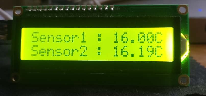
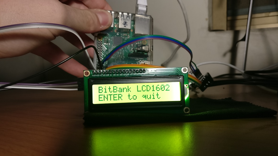
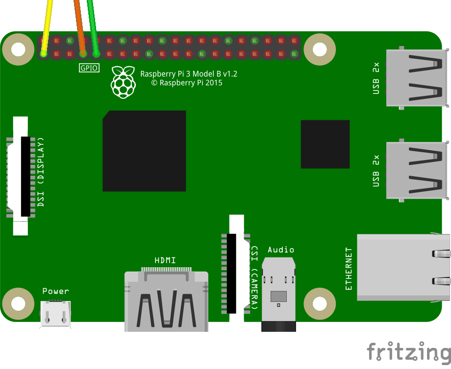
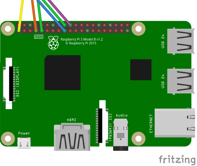
Since you made it here, great! Your Raspberry Pi should have one or more DS18B20 thermal sensors connected, like the image below.

sensor2.png

Now that we have our DS18B20 thermal sensor connected to our Raspberry Pi, it’s time to do some programming to read out the temperature! Our application will need to be able to the following tasks:

  1. Discover all the DS18B20 sensors (in my case, I’ve connected 2 but this application should handle an arbitrary number of sensors).
  2. Assign a friendly name so we’ll know which sensor is which and store them in a list.
  3. Retrieve and parse the information from the device.
  4. Do whatever necessary with the gathered information.

1) Discover all the DS18B20 sensors

First and foremost, our code cannot just assume that devices just exist on the system – we’ll need to go and discover these devices. Since the DS18B20 makes use of the 1-Wire protocol, devices will live under the /sys/bus/w1/devices/ directory. Therefore, our code will need to devices living under this directory, whose names start with 28 since all DS18B20 device names will start with 28. Let’s start by knowing how many devices are connected.

typedef struct Sensor
{
    char *SensorName;
    FILE *SensorFile;    
} Sensor;
 
typedef struct SensorList
{
    Sensor **Sensors;
    int SensorCount;
} SensorList;

DIR *dir;
struct dirent *dirEntry;

SensorList *sensorList = malloc(sizeof(SensorList));
sensorList->SensorCount = 0;

if(!(dir = opendir("/sys/bus/w1/devices/")))
    return sensorList;

while((dirEntry = readdir(dir)))
{        
    if(strncmp(dirEntry->d_name, "28", 2) == 0)
    {
        sensorList->SensorCount++;
    }
}

2) Assign a friendly name so we’ll know which sensor is which and store them in a list

Now that we’ve discovered the devices connected to the system, it’s time to save a reference and optionally a friendly name as well. Logic mostly applies from step 1.

sensorList->Sensors = malloc(sizeof(Sensor*) * sensorList->SensorCount);
Sensor **currentSensor = sensorList->Sensors;   

int sensorNamesAllocated = 0;
while((dirEntry = readdir(dir)))
{        
    if(strncmp(dirEntry->d_name, "28", 2) == 0)
    {   
        char *sensorName;
        if(sensorNamesCount > sensorNamesAllocated)
        {
            sensorName = strdup(*sensorNames);
            sensorNames++;
        }
        else
        {
            sensorName = strdup("Sensor");
        }

        char sensorFilePath[64];     
        sprintf(sensorFilePath, "%s%s%s",  "/sys/bus/w1/devices/", dirEntry->d_name, "/w1_slave");
        *currentSensor = GetSensor(sensorFilePath, sensorName);
        currentSensor++;
    }
}

Sensor *GetSensor(char *sensorId, char *sensorName)
{
    Sensor *sensor = malloc(sizeof(Sensor));
    sensor->SensorFile = fopen(sensorId, "r");
    sensor->SensorName = sensorName;
    return sensor;
}    

3) Read the temperature from the device

This is the most exciting part – we actually get to read the temperatures! Using the sensor information we got from steps 1 and 2, we can get the device, open it as a file, extract the readings and parse it accordingly. Using the FILE API makes it very easy to do so – grab all the contents and store it in a buffer. As mentioned in the first tutorial, the content of the file looks as follows –

0b 01 55 05 7f 7e 81 66 bf : crc=bf YES
0b 01 55 05 7f 7e 81 66 bf t=16687

We’re only intereested in the t= component, so some string manipulation and float conversion will take the 16687 and convert it into 16.687C. We’re also doing some range checking since the DS18B20 is rated between -55C and +125C

   
long deviceFileSize;
char *buffer;

FILE *deviceFile = sensor->SensorFile;
fseek(deviceFile, 0, SEEK_END);
deviceFileSize = ftell(deviceFile);
fseek(deviceFile, 0, SEEK_SET);

buffer = calloc(deviceFileSize, sizeof(char));

fread(buffer, sizeof(char), deviceFileSize, deviceFile);
char *temperatureComponent = strstr(buffer, "t=");
if(!temperatureComponent)
{
    free(buffer);
    return -1;
}

temperatureComponent +=2; //move pointer 2 spaces to compensate for t=

float temperatureFloat = atof(temperatureComponent);
temperatureFloat = temperatureFloat / 1000;

if(temperatureFloat  125)
    temperatureFloat = 125;    

free(buffer);
return temperatureFloat;

4) Do whatever necessary with the gathered information

We now have the information at hand, great! We can do many sort of things with it, such as sending an email, activating some other device or whatever is necessary. For demo purposes, we’re simply going to output the contents to the console just to see it working. This is in a loop so we’ll keep reading the temperature until the application exits.

 while(1)
    {
        for(int i = 0; i SensorCount; i++)
        {
            char dateTimeStringBuffer[32];
            strftime(dateTimeStringBuffer, 32, "%Y-%m-%d %H:%M:%S", localtime(¤tTime));

            float temperature = ReadTemperature(sensorList->Sensors[i]);
            printf("%s - %s - %.2fC\n", dateTimeStringBuffer, sensorList->Sensors[i]->SensorName, temperature);
        }       
    }

To try out the code as a whole solution, grab a copy from GitHub – https://github.com/albertherd/DS18B20Reader

In a terminal with git and cmake installed, run the following commands

git clone https://github.com/albertherd/DS18B20Reader
cd ./DS18B20Reader
cmake . && make && ./DS18B20Reader "Sensor"

If the output looks like the below, congratulations!

ds18b20 tutorial sample output.png

In the next tutorial, we’ll pick up from here and we’ll start outputting the content on an LCD1602! Until the next one.

Connecting a LCD1602 with an I2C module to your Raspberry Pi – Raspberry Pi Temperature Monitoring Part 2

The LCD1602 is a very famous LCD that can be connected to various devices such as the Raspberry Pi. The LCD1602 on its own is quite tricky to wire it up since it requires 16 pins to be connected. The LCD1602 can also be purchased with an I2C module, which reduces the amount of pins needed to just 4.

For this tutorial, we’ll be working with a LCD1602 with an I2C module. I got mine from AliExpress for around $2.50. Make sure to grab a set of jumper cables as you’ll need them to connect the LCD to the Raspberry Pi. I got mine from AliExpress as well for around $1.50.

IMG_20190102_110607.jpg

img_20190109_230900

Let’s start by wiring it up. We have 4 pins connect – GND (ground), VCC (power, 5V), SDA (data line) and SCL (clock line). GND and VCC can be connected to any equivalent GND and 5V pin. SDA and SCL should be connected to pins BCM 2 and BCM 3 accordingly.

lcd1602_i2c_raspberrypi

img_20190109_231321

If you’re following the Raspberry Pi Temperature Monitoring Part 1 and connected the DS18B20 temperature sensors, you should now have the following configuration.

lcd1602_i2c_ds18b20_raspberrypi

img_20190109_232649

Great! We’re done from the hardware’s side – let’s start configuring our Raspberry Pi to communicate with our LCD.

Firstly, let’s enable I2C from the Raspberry Pi Config. Fire up the raspi-config to get started: sudo raspi config

Now navigate to Interfacing Options => I2C => Enable I2C

raspi-config-interfacing-options

raspi-config-interfacing-options-i2c

Now that we’ve enabled I2C communication, it’s time to start development! We’ll need to get some tools before we start working though, so fire up a shell and input:

sudo apt-get install i2c-tools.

Once that’s done, the LCD is ready to be programmed! Let’s make sure that the LCD is properly connected and working. In a shell, type:

i2cdetect -y 1.

The output should be something like the below. Note the number outputted by the command; will be needed later on. We’ll need this address when we’re trying our demo code. In this case, the address is “27”.

i2cdetect

Great! Now, it’s time to test out our display and see if it works! We’ll be using a Github library – https://github.com/albertherd/LCD1602. This has been forked from https://github.com/bitbank2/LCD1602. We’ll be using my fork since the original repository has an unresolved issue with clearing the display.

After you’ve cloned the repository in your working directory, it’s time to use the address (27 in my case) obtained earlier. Open the main.c and find the call to lcd1602Init and change second parameter. This is how it looks in my case:

lcd1602Init(1, 0x27);

Now it’s time to compile and run our code. If all goes well, we should be getting some text on the screen. You can change the text to whatever you’d like by changing the following lines in main.c.

lcd1602WriteString("BitBank LCD1602");
lcd1602SetCursor(0,1);
lcd1602WriteString("ENTER to quit");

Build and run using the following commands:

make
make -f make_demo
./demo

The screen should look like the below:

IMG_20190110_231937.jpg

Great! Now we’ve successfully connected our LCD1602 to our Raspberry Pi and we’re able to output content on it!

In the next part of this tutorial series, we’ll start by capturing the temperature using the sensor in our first part of the tutorial and outputting it! Stay tuned.

Connecting a DS18B20 thermal sensor to your Raspberry Pi – Raspberry Pi Temperature Monitoring Part 1

A project that I’ve been working on during the Christmas holidays was to hook up some thermal probes to my Raspberry Pi, just to play around. This tutorial simply follows the steps that I’ve taken to achieve so.

You’ll need:

  • Raspberry Pi, any flavor as long as it has GPIO headers available. I had a Raspberry Pi 2, so I used that.
  • You’ll also need the usual suspects – USB to MicroUSB to hook it up to power, HDMI to connect it to a display for initial configuration and an ethernet port to manage it through SSH. I highly recommend configuring SSH rather than using the device itself. This tutorial assumes you’re using SSH.
  • A DS18B20 sensor – I’d suggest getting one which includes a Plugable Terminal to avoid soldering – just wire it up and you’re good to go. I got mine from AliExpress
  • Also make sure your kit has 3 jumper cables. They are typically included. Just to be sure, I also got a set of female to female jumper cables from AliExpress though I did not use them for the DS18B20 sensor.

All right, let’s wire it up! The DS18B20 sensor requires three pins – data, VCC (3.3V), and ground. Connect the wires as below. Data is yellow, VCC is red and ground is black.

IMG_20190102_105252

Connect the 3 pins using the jumper cables as shown below.
sensor1.png

IMG_20190102_105726

We’ll also need to instruct the Raspberry Pi that we’re going to connect the DS18B20 sensor. This sensor makes use of the 1-Wire protocol, so let’s activate it:

  • Connect to the Raspberry Pi using SSH
  • Let’s start by editing the config file that the Raspberry PI parses every time it boots up: sudo nano /boot/config.txt
  • Go to the end of the document and input the following. Specifying gpiopin=4 is actually optional since by convention, 1-wire devices are expected on gpiopin 4 on the Raspberry Pi.
    # Enable OneWire Protocol
    dtoverlay=w1-gpio;gpiopin=4
  • Time to reboot the Raspberry Pi sudo reboot
  • Once the Raspberry PI reboots and you re-connect using SSH, it’s time to get data from the sensor! Let’s find the 1-wire devices connected to the system. Let’s start by browsing to the appropriate directory. cd /sys/bus/w1/devices
  • Great! Let’s now see the devices attached to the Raspberry Pi. ls
  • This will get the devices attached using the 1-Wire protocol. You should have a device called 28-xxxxxxxxxxxx (where x stands for your unique 12 digit serial number). Let’s now browse the device. Mine is 28-02199245e07b, so let’s use it an example. cd 28-02199245e07b
  • Once you access the device, there should be a file called w1_slave. Let’s see the contents of the file. cat w1_slave
  • The file should look like this:
    0b 01 55 05 7f 7e 81 66 bf : crc=bf YES
    0b 01 55 05 7f 7e 81 66 bf t=16687
  • If the file looks like the above, great! The temperature component is t=16687. The temperature in this case is 16.687 °C

We also can take this to the next level and add another thermal probe! Attach it as shown below.
sensor2IMG_20190102_110134

This will require re-editing the /boot/config.txt. Let’s do it!

  • Re-open /boot/config.txt – sudo nano /boot/config.txt
  • Go to the end and add the following. I chose pin 24 because it’s easy to wire since it’s close to a 3.3v and ground. dtoverlay=w1-gpio;gpiopin=24
  • Close and save, then cd /sys/bus/w1/devices
  • You should now see two devices as 28-xxxxxxxxxxxx

Of course, at this stage we did get the temperature, but it’s not really usable. We can get access to this information programmatically – this is what we’ll be doing in the next part of this tutorial. We’ll also be eventually showing the information on a separate LCD screen! Stay tuned!

Group files into folder structure by date using PowerShell

Lately I was sorting out around 5000 files worth of pictures and videos taken out from a mobile phone, to upload them on a cloud drive. To make this task more manageable, I wanted to separate these files out, firstly by file type and then by date. This will make the folders far more smaller and therefore easier to upload these files to the cloud folder by folder.

Grouping such several files manually will be very tedious and error-prone. This task is a perfect candidate to be scripted out; this is exactly what I did. Since this may be helpful to other people going through such task, I decided to share this script.

All the script requires is a source path and a target path – anything else is handled by the script. It has several assumptions, such as it always moves, never deletes a file. Customising the script is easy and only requires basic programming knowledge.

Check it out here or below: https://github.com/albertherd/GroupFilesPowershell/blob/master/GroupFiles.ps1

Param(
    [Parameter(Mandatory=$true)]
    [string]$sourcePath,
    [Parameter(Mandatory=$true)]
    [string]$targetPath
)

$global:fileTypeLookup = @{};
$folderDateTimeFormat = "MM-yyyy"

function Copy-FilesIntoFoldersByMonthAndType{
    param()

    $files = Get-ChildItem -Recurse -File -Path $sourcePath
    $filesProcessed = 0

    foreach($file in $files){
        $folder = Get-DirectoryForFile $file
        Copy-Item $file.FullName -Destination $folder

        $filesProcessed++
        Write-Progress -Activity "Grouping files" -Status "$($filesProcessed) out of $($files.Count) grouped" -PercentComplete (($filesProcessed / $files.Count) * 100)
    }
}
function Get-DirectoryForFile{
    param($file)

    $monthYearDirLookup = Get-FilePathDictionary $file
    $modifiedTimeMonthYearInternal = $file.LastWriteTime.ToString("MMyyyy")

    if($monthYearDirLookup.ContainsKey($modifiedTimeMonthYearInternal)){
        return $monthYearDirLookup[$modifiedTimeMonthYearInternal]
    }

    $extensionWithoutDot = $file.Extension.Substring(1, $file.Extension.Length - 1)
    $dateFolderFileName = $file.LastWriteTime.ToString($folderDateTimeFormat)
    $newPath = $targetPath + "\" + $extensionWithoutDot + "\" + $dateFolderFileName
    $path = New-Item -ItemType Directory $newPath -Force

    $monthYearDirLookup[$modifiedTimeMonthYearInternal] = $path.FullName
    return $path.FullName
}

function Get-FilePathDictionary{
    param($file)

    if($global:fileTypeLookup.ContainsKey($file.Extension)){
        return $global:fileTypeLookup[$file.Extension]
    }

    $global:fileTypeLookup.Add($file.Extension, @{})
    return $global:fileTypeLookup[$file.Extension]
}

Copy-FilesIntoFoldersByMonthAndType

In my case, it generated the below folder structure:

FolderStucture

Far more manageable than one flat folder of 38.8 GB folder, for sure!

Until the next one.